POWER AMPLIFIERS PART ONE: AMPLIFIER CLASSES, AKA ‘THE BEAUTIFUL INVENTION OF THE TRANSISTOR’.
Electrical power is the product of voltage (V, measured in volts) and current (I, measured in amperes, often shortened to amps). In electrical circuits in analogue mixers and processors, the voltage is most commonly set to around ±15V to achieve a good signal to noise ratio. To prevent components from heating up too much, currents are kept low; in the milli- and micro-amp range, so the power consumption is in the milliwatt range.
Power amplifiers are an exception; instead of milliwatts, loudspeakers in sound reinforcement systems need several hundred or sometimes several thousand watts to produce a high enough sound pressure level (SPL). For safety reasons, the output voltage needs to be below 50V, so the only way to generate so much power is to apply a high current.
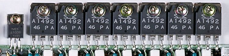
Until the mid 1950s, electronic circuits in power amplifiers used vacuum tubes, capable of producing only moderate output power. Because vacuum tubes heat up their power efficiency was low, as was their reliability. However, in 1947 everything changed when Bell Laboratories invented the point contact transistor. This electronic component had three terminals: Base, Collector and Emitter, with a small current from Base to the Emitter causing a much larger current from Collector to the Emitter. This current amplification is precisely what a power amplifier needs! An alternative form is the Field Effect Transistor - FET, where the terminals are renamed Gate, Source and Drain. Both offer the ideal concept to build a power amplifier, using a small component without moving parts, without the vacuum tube’s vulnerable glass housing and life-shortening heat dissipation. When the first ‘transistor radios’ came to market in the mid-50s, they were pitched as ‘solid state’ - synonymous to compactness and reliability.
There are basically three methods of using transistors to make a power amplifier. The most simple is named ‘class A’, using a single transistor supported by a single line power supply. This method produces a high linearity at low signal levels but, at the same time is very inefficient because the ‘zero state’ of the amplifier - where no power goes to the loudspeaker - still requires the transistor to endure half of the maximum current. This causes most power to be dissipated in the transistor as heat, with just a small portion going to the loudspeaker.
A ‘class B’ circuit solves this problem, using a double power supply and two transistors: one for the audio signal’s positive phase and another for the negative phase. This arrangement allows for the transistors to be inactive in the ‘zero state’, significantly increasing power efficiency. But there is a down side; transistors need an initial Base to Emitter voltage to work and this introduces distortion, especially at low signal levels. To solve this, an additional circuit is applied to set both transistors to conduct just a small current at zero state, partially using them in ‘class A’ mode. This combined application is named ‘class AB’, combining a high signal quality with a better power efficiency, an is used in almost all power amplifiers not using the third method...
The third method is ‘class D’ (following the class C method which is not suited for high quality audio). The ‘D’ does not stand for ‘digital’, but uses transistors as switching components to generate a high frequency pulse code with an energy density following an audio signal’s voltage. To convert the output high frequency pulse back to the original audio signal, a passive filter has to be applied, using the loudspeaker as a filter-component. This has the disadvantage of the output being affected by the loudspeaker’s properties. Also, because the output pulse signal operates at radio frequencies, there are legal implications with regards to electro-magnetic emissions. The big advantage of the class D method is the extremely high efficiency: almost all of the power goes to the loudspeaker and very little is dissipated in the amplifier. This is the reason why class D is increasingly popular.
There are many more power amplifier classes, for example class G, H and TD, all using a class D type circuit as power supply driving a class AB power stage, resulting in an amplifier that combines class AB quality and stability with class D efficiency. Yamaha’s application is named Energy Efficient Engine or ‘EEEngine’, as applied in XP, PC, T and TN series power amplifiers. However, class D circuit designs have evolved over the years to support high quality performance, becoming the dominant class for power amplifiers.